spur gear design
Spur Gears - Roy Mech
Spur Gear Design. The spur gear is is simplest type of gear manufactured and is generally used for transmission of rotary motion between parallel shafts. The spur gear is the first choice option for gears except when high speeds, loads, and ratios direct towards other options. Other gear types may also be preferred to provide more silent low
Learn More
Home - Spur Gear
The design and construction of a spur gear significantly influence its performance. To do their jobs effectively and efficiently, they need to be fabricated from high-quality materials and to precise dimensions. The dimensional measurements of each feature are integral to how a specific gear functions. As such, when an industry professional
Learn More
spur gear design - SlideShare
spur gear design 2. Machine Design II Prof. K.Gopinath & Prof. M.M.Mayuram Indian Institute of Technology Madras tF V W ( 1000 7.5) where d is the pitch diameter of the gear in millimeters and n is the rotating speed in rpm and W power in kW. 7.2 SPUR GEAR - TOOTH STRESSES Fig. 7.2 Photo-elastic Model of gear tooth Stresses developed by Normal force in a photo-elastic model of gear tooth as
Learn More
Spur Gears: A Complete Guide - What are they, Types and Uses
31/03/ · Spur Gears Applications. Spur gears are used to transfer motion and power from one shaft to another in a mechanical setup. This transference can alter machinery’s operating
Learn More
Design of Spur gear - Lesics
05/02/ · Fig:1 Input and output parameters for a gear design Fig:2 A general spur gear nomenclatures Design for space constrains. The designed gear system should fit within a
Learn More
Gear Design | Spur Gears
This video lecture will teach you how to design spur gears for mechanical strength, dynamic load and surface durability. Here design is carried out to meet all input requirements conforming to AGMA
Learn More
Spur Gear Calculator and Generator Download DXF, SVG or CSV Excel
Gear Design and Engineering . Spur Gear Calculator and Generator - Download DXF, SVG or CSV Excel format files . Simular: Spur Gear and assembly Builder. Spur Gear Generator is unitless: you may choose inches, cm or millimeters when importing your DXF file as you will have the same value for D/P as it is set above or as imported (SI or imperial
Learn More
PDF) DESIGN AND ANALYSIS OF SPUR GEAR
Gear is the special division of Mechanical Engineering concerned with the transmission of power and motion between the rotating shafts. In this study, a lathe machine tumbler gear mechanism used for threading purpose is taken and applied finite element analysis methodology on each metallic spur gears and also FEA analysis is done for hybrid spur gear with same applied load
Learn More
spur gear | Mail:[email protected]
Spur gears are widely accepted as the most efficient type of gearing solution, when the application of transmitting power and uniform rotary motion from one parallel shaft to another is required. More Scientific Gear Tooth Design: It avoids local stress concentration caused by straight tooth edge extrusion, and tooth surface friction is
Learn More
Spur Gears: A Complete Guide - What are they, Types and Uses - Grob Inc
Spur gears feature a simple, compact design that makes them easy to design and install, even in limited or restricted spaces. Constant Speed Drive. These gears increase or decrease shaft speed with a high degree of precision at a constant velocity. Reliability.
Learn More
Spur Gear Terminology & Formulas | Pitch Diameter, Pressure Angle
Working Depth: The depth to which a tooth extends into the space between teeth on the mating gear. Formulas for determining some of these terms include: Addendum. 1.0 ÷ diametral pitch. Clearance. 0.157 ÷ diametral pitch. Diametral Pitch. Number of teeth ÷ pitch diameter. Number of Teeth.
Learn More
Spur Gear Theory and Design - IJARIIE
Spur Gear Theory and Design Soumitra Bhattacharya, M.Tech (Mech), Professional Member of ASME ABSTRACT Gears are commonly used for transmitting motion and power. In precision
Learn More
PDF) Spur Gear Theory and Design
SPUR GEAR: Spur gears are the most common type of gears. They are used to transmit rotary motion between parallel shafts i.e., they are usually cylindrical in shape, and the teeth are straight and parallel to the axis of rotation. Sometimes many spur gears are used at once to create fvery large gear reductions.
Learn More
MD-12 Spur Gear Design - University of Northern Iowa
12. Spur Gear Design and selection Objectives • Apply principles learned in Chapter 11 to actual design and selection of spur gear systems. • Calculate forces on teeth of spur gears, including impact forces associated with velocity and clearances. • Determine allowable force on gear teeth, including the factors necessary due to
Learn More
SolidWorks Tutorial | Design of Spur Gear
11/09/2022 · In this video, the spur gear is created with basic commands in an easy way.Follow my FB page: https://www.facebook.com/jahanstuddy11If you are interested to
Learn More
Spur Gear Design Tool Calculator - Engineers Edge
Spur Gear Design Tool Calculator per. ANSI B6.1 Formulas for Tooth Parts, 20-and 25-degree Involute Full-depth Teeth ANSI Coarse Pitch Spur Gear Tooth Forms. The spur gear diametral pitch system isintended to provide a series of standard tooth sizes, the principle being similar to the standardization of screw thread pitches.
Learn More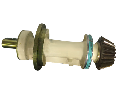
Gear Design Equations and Formula | Circular Pitches and Equivalent
Spur Gear design formula for geometry, pitch, tooth clearance and critical functional data. (Inch Units Applicable for Constants) Spur Gear Design Calculator Where: φ = Pressure Angle a = Addendum a G = Addendum of Gear a P = Addendum of Pinion b = Dedendum c = Clearance C = Center Distance D = Pitch Diameter D G = Pitch Diameter of Gear
Learn More
PDF Spur Gear Design - West Virginia UniversityPDF
Spur Gear Design MAE 342 -Dynamics of Machines Spur Gear Design MAE 342 -Dynamics of Machines 2 Idealized Spur Gears •The speed ratio is given by: R R3 2 ω3 ω2 MAE 342 -Dynamics of Machines 3 Tooth pitch •However, in order for the gears to mesh, they must have the same tooth pitch MAE 342 -Dynamics of Machines 4 Tooth pitch
Learn More
Spur Gear: Definition, Types, Terminology, Advantages, Disadvantages
Spur Gear Disadvantages: Spur Gear Application: Spur Gear is the most used gears, having Straight teeth and are mounted on two or more parallel shafts. The design of spur gear is simple. The spur gear is also known as slow-speed gears due to noisy operation at high speed. When the spur gears are Engaged the contact will be to the Entire width
Learn More
Design of Transmission Systems - Spur Gears - Google
Spur Gears. The simplest and the easiest type of gear is the spur gear. The spur gear transmits power and motion between parallel shafts and it is widely used in all common transmission applications. The teeth of gear is parallel to the axis of shaft. The following fig shows a pair of spur gear.
Learn More
PDF Spur Gear Theory and Design - IJARIIEPDF
SPUR GEAR: Spur gears are the most common type of gears. They are used to transmit rotary motion between parallel shafts i.e., they are usually cylindrical in shape, and the teeth are straight and parallel to the axis of rotation. Sometimes many spur gears are used at once to create very large gear reductions.
Learn More